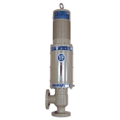
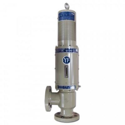
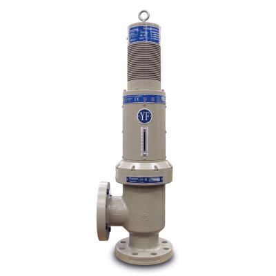
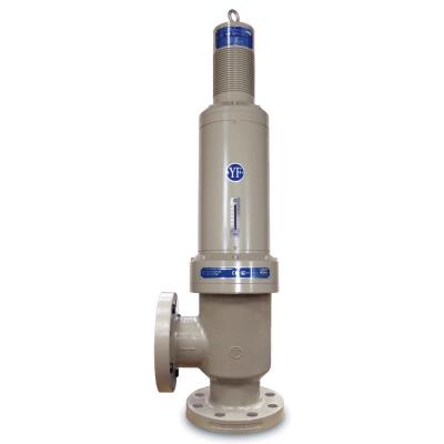
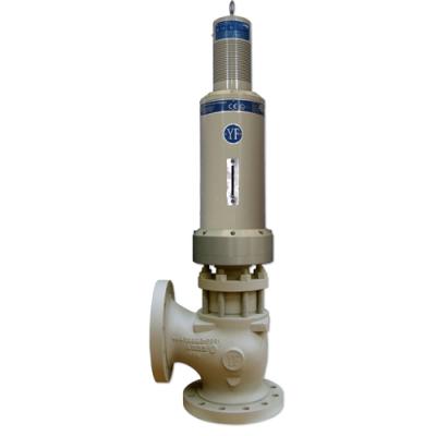
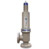
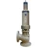
YF 3010 Series EMA Choked Flow Gas Control Valves
The Young & Franklin 3010 Series sonic flow Gas Control Valves (GCVs) are electro-mechanically actuated (EMA)
to provide excellent speed and valve position accuracy. This GCV electronically homes on power cycle and has a turndown ratio of ~100:1. The entire YF 3010 Series is certified for use in hazardous locations around the world and available in a range of sizes suitable for industrial or power turbines of any size.
The valve body is coupled to an actuator assembly that contains a fail-safe spring to quickly close the valve, halting fuel flow in the event of a power failure or turbine trip condition. Shock absorbers protect the actuator drive mechanism and valve seats during rapid closing thus ensuring reliable operation, and independent position feedback can be obtained via 2 optional LVDTs. The complete system provides precise fuel flow delivery with reliable operation. No routine maintenance is required.
| Avaliable Sizes |
1"
|
1"
|
2"
|
2"
|
3"
|
3"
|
4"
|
6"
|
|
| Flow Profile |
Linear
|
Non-Linear
|
Linear
|
Non-linear
|
Linear
|
Non-linear
|
Linear
|
Linear
|
|
| Rated Cg |
Up to 311 Cg
|
Up to 1200 Cg
|
Up to 2900 Cg
|
Up to 4300 Cg
|
Up to 6600 Cg
|
||||
| Estimated Dry Weight |
75 lbs. (34 kg)
|
95 lbs. (43 kg)
|
160 lbs. (54 kg)
|
255 lbs. (116 kg)
|
370 lbs. (168 kg)
|
||||
| Slew Time |
≤250 ms
|
≤250 ms
|
≤350 ms
|
≤700 ms
|
|||||
| Trip Time |
≤250 ms
|
≤350 ms | |||||||
| Maximum Operating Pressure |
Carbon Steel: 620 psig (42.7 barg) • Stainless Steel: 497 psig (34.2 barg)
|
||||||||
| Burst Pressure |
5x Maximum Operating Pressure
|
||||||||
| Valve Flange Size |
ASME B 16.5 Class 300 Flange
|
||||||||
| Fluid Temperature Range |
-0°F to 450°F (-18°C to 232°C)
|
||||||||
| Ambient Temperature Range |
-4°F to 212°F (-20°C to 100°C)
|
||||||||
| Mean Time Between Service |
96,000 Hours
|
||||||||
| Mean Time Between Failures (MTBF) |
290,000 Hours
|
||||||||
| Valve Materials |
Available in Carbon Steel or Stainless Steel (NACE MRO175 Compliant)
|
||||||||
| Bandwidth/Frequency Response |
Customizable up to 23 Hz with 3dB attentuation
|
||||||||
| Independent Feedback |
2 LVDTs (Optional)
|
||||||||
| Motor Coil |
Class F insulation (311°F, 155°C)
|
||||||||
| LVDT Wiring |
6.56 ft (2 m) Flying Lead or MIL Connector
|
||||||||
| Motor Wiring |
3 ft (.91 m) Flying Lead or 32.8 ft (10 m) Jacketed Cable
|
||||||||
| Visual Position Indicator |
Yes
|
||||||||
| Ingress Protection |
IP65
|
||||||||
| Stem Leakage |
Zero Leakage, as shipped
|
||||||||
| Seat Leakage |
Class IV per ANSI FCI 70-2
|
||||||||
| Failure Mode |
Spring to drive valve to Safe position (Fail Close)
|
||||||||
| Environmental |
MIL-STD-810 - Shock and Vibration
|
||||||||
| Command |
4-20 mA Position, -8 to +8 mA Triple Redundant Velocity
|
||||||||
| Certifications |
Standard Assembly: Class 1 Div 2, Group B, C & D, T3
With Optional LVDTs: Class 1 Div 2, Group B, C & D, T3
|
||||||||
| Attachment | Size |
|---|---|
| 580.89 KB |


 View all Electrically Actuated Gas Control Valves